


This project is a robot vehicle that can be controlled through any computer wirelessly using a WiFi link. It transmits real-time video to the controlling computer using the same link. The video transmitting camera mounted on it is 360° rotatable. It also has hurdle detection and light sensitivity feature.
Usually robots are controlled through a remote using an RF link which is subject to attenuation, noise and has a very limited range as well. This project features a robot that uses WiFi 802.11G standard for its control signals through TCP/IP protocol, which has flow control. This enables uninterrupted and reliable transmission of control signal to the robot vehicle. WiFi support high data rates which enables good quality uninterrupted video transmission from the robot to the computer. Camera rotation is done by mounting an IP-camera over a geared motor controlled through a bridge circuit. Hurdle detection is done using Ultrasonic sensors which work on sonar principle. Light sensing capability is another supporting feature added to the robot for its flexible operation, it is done by using Light dependent resistors.
This robot is capable of moving with speed of 12Km/h up to a distance of 200m from the controlling computer. It has rechargeable batteries which can support 1.5 hours of full operation. WiFi link enables the use of access points between the robot and the computer thus the operating range can be increased several times. It is applicable is areas like blocked tunnels, pipe lines and enemy zones which are not reachable due to high risk level, blockage or because of our physical limitations.
To download everything related to this project (i.e CODES, CLIENT APPLICATION, REPORT, PRESENTATIONS) CLICK HERE
PROPOSED SYSTEM AND FEATURES:
This Project is a robot vehicle which is wirelessly controllable through any laptop, it transmits live video wirelessly to the controlling laptop, it can detect hurdles and obstructions which comes in its path way, and can also sense dark places and efficiently uses its lights to support efficient use of camera even in dark places.
Robot vehicle has the following features enabled:
- Wirelessly controlled and maneuvered through a laptop using a WiFi link.
- Controlling GUI designed in visual basic 6.0 which can control the robot vehicle movement.
- Hurdle detection feature with which any hurdle in its path is detected and the robot stops.
- Wi-Fi enabled transmission of live digital video to the controller laptop or PC.
- 360’ degree Rotate able Camera for capturing 3Dimentional view.
- Light sensitivity; it would turn its lights on recognizing if it is dark.
- Horn feature; it has a horn which can be used wirelessly.
- Incredibly increasable range using access points.
PROJECT LAYOUT:
Following is a rough project block diagram.

This layout gives a brief understanding of the question that “HOW DOES IT WORK?” There is TCP/IP communication between the controlling computer and the router (WRT series router) that is mounted on to the robot car. The router receives and sends the control signals and it serially communicates with the microcontroller. The camera is attached to the router and it is also mounted on the robot vehicle. The camera used is an IP CAMERA and it is 360’ rotate able CW &CCW.
Robot vehicle has the following features enabled:
IMPLEMENTATION:
This project has been developed in seven stages namely,
- Wifi link development.
§ The router hack (serial port development).
§ Firmware upgrade.
§ Developed Serial port testing.
§ Car server development (code development & installation in router).
§ Interface development (GUI).
- Hurdle detection.
§ Ultrasonic method.
§ IR method.
- Light sensitivity.
- Video link development and configuration.
- Camera rotation.
- Power source development.
- Integration of modules.
- Range, speed and power testing.
WiFi-Linki Development:
For the wifi link we have used Linksys WRT54GL v1.1. This router works as a server and communicates with the controlling laptop. The reason of using this particular router is that it is intended to be hacked by the company. It is an open source router which enables the use of many third party firmware and many hacks as well. We have developed a serial port on the router so that it can communicate with the microcontroller present on the robot vehicle.

HOW to develop a serial port on router:
The reason why we need a serial port is so that the router will be linked to the microcontroller and to communicate with microcontroller its needs a serial port as microcontrollers do serial communication. microcontroller takes seriall signal from the router and feeds it to the car circuit.
Since the soldering in this mod is not very difficult, this is a good mod to attempt if you're just starting out in electronics and are looking to get some soldering experience. The electronics part is not too difficult, but the result can be very useful to control external electronics or just to have a serial console. There are mechanical case modifications that are required as well, which makes this mod a bit more tricky than just a soldering project


Disaasembly:
- Remove the 'void warranty' sticker!Unscrew the two wifi antennas.
- The front blue faceplate snaps apart from the black body. It takes some force to seperate them, but they will come apart. Place your thumbs on the blue legs while holding the black body and push on on the blue faceplate to seperate them.
- After the casing has been removed, remove the screws holding the circuit board to the plastic bottom so that the router PCB is free.
Soldering the JP2 Header:
Locate the JP2 header on the router board. the header pinouts are as follow:
| Pin 1: 3.3V | Pin 2: 3.3V |
| Pin 3: Tx (ttyS1) | Pin 4: Tx (ttyS0) |
| Pin 5: Rx (ttyS1) | Pin 6: Rx (ttyS0) |
| Pin 7: NC | Pin 8: NC |
| Pin 9: GND | Pin 10: GND |
Electrical modifications:
The router uses 3.3V/GND for it's serial line voltage levels. We need to use a line level convertor that converts the 3.3V/GND to the +/-12V standard for RS232 serial communication. Technically, the right chip to use for this project is a MAX3232, however I've used both the MAX232 and MAX233 chips and they work fine as well. You could use any one of these 3 chips. MAX233 is nice because there is no need of external capacitors with it.


To Test TTYS/1 (Port we will be using /THE MALE DB9 connector):


Connect the FOUR pins (Forward , backward, right , left) coming from the microcontroller to this IC's respective pinouts.
THE FIRMWARE UPGRADE:
 |
| MAX232 circuit diagram |
 |
| MAX 233 circuit diagram |
This should look like this:


NOW The Software Part of this Hack:
The process described here will test both serial ports using X-WRT, a linux distribution for the WRT54GL that has a nice web interface. well to know how to install firmware image on to the router see (the firmware upgrade) section of this project.these ports should work fine for the other distributions as well.
After installing the firmware image, acess the web interdace (by default: http://192.168.1.1/). The first screen will ask you to set a new password. Set a new password and remember it!
To Test TTYS/0 (Console port /THE FEMALE DB9 connector):
- Connect a serial cable form the female DB9 connector to your PC. cable for this is usually called CROSS CABLE in markets.
- Open a hyperterminal connection using the settings showns (115200,8N1)
- Reboot the router.
- you should see a bunch of kernel messages. Hit enter at the terminal and you should see a screen like that looks like the one below.


- Connect a null modem cable between the TTS/1 DB9 connector and your PC.
- Open a hyperterminal connection using the settings shown in the figure (9600,8N1).
- SSH in to the router (username is "root", Password is what you have set earlier) PUTTY is a good SSH software for Windows.
- Enter the command: echo "hello world" > /dev/tts/1
- confirm that you see "hello world" on your serial console in hyperterminal, if you see it means the hack is perfectly working. Consult these pictures for help.
MICROCONTROLLER CIRCUIT :
Microcontroller used in this project is a simple one that is (PIC 16F628A). It is easily available easy to use and cheap as well. The microcontroller is connected with the router, when router receives a control signal it passes it on to the microcontroller which then handles the further operation. Microcontroller compared the received values with the ones already coded in it and does the corresponding operation. For example if it receives value 8 it sends a ‘1’ to a pin responsible for the forward movement of the robot.
As for testing purposes a 3.3V coming from router were converted to 12V so now it cannot be fed directly to the microcontroller and it needs to be converted back so max232 is again used with the microcontroller and a male DB9 connector is also added as shown in figure 
Here is the code to burn on the microcontroller: DOWNLOAD CODE HERE
To download the Hex file directly : DOWNLOAD HEX HERE
CAR RECEIVER IC:
Computer connects to the router, router connects to the microcontroller, and microcontroller connects to the CAR RECEIVER IC and feeds the signal to it. Disassemble your car and look for the receiver IC usually there is a realtek IC in there, search the IC data sheet on internet and look for the FORWARD BACK RIGHT LEFT pinouts. here is the diagram for the one i had in my car.

lINKSYS allows us to upgrade the firmware and install a third party firmware that gives us extra features, but the warantee is gone once you install a third party firmware. Here we have used X-WRT a graphical extension to OPENWRT white Russian v0.9. To install the firmware SEE THIS PAGE. You can have the image file of X-WRT here.
Why a third party firmware has been used? Answer to this question is that only third party firmware allows installing the desired code into the router’s memory and by doing so that router could be used for our desired purpose. Secondly for using serial port it had necessary to make some changes in the boot file used by the router an openwrt-xwrt which can be used to do so.
CAR SERVER DEVELOPMENT:
There are pieces of this software which makes this project possible:
VB6 wifi robot client application (runs on windows), the car server which is in C and runs on the router running X-WRT and the microcontroller firmware which i have provided.
Installing the Car Server into the router:
The router should first be connected to perform this operation. so connect to the internet first.
SSH into the router using PUTTY type :(dont write the hash#)
# cd /tmp
# wget www.jbprojects.net/projects/wifirobot/carserver_1_mipsel.ipk
#ipkg install ./carserver_1_mipsel.ipk
Getting the serial port working:
Now we need to configure the male DB9 connector or the TTS/1 connector which we are using so for that SSH into the router using putty and write the following lines to install the serial port package into the router.(dont write the hash #)
#ipkg upgrade
#ipkg install setserial
#cd /usr/sbin
#wget http://www.jbprojects.net/projects/wifirobot/stty.tgz
#tar -zxvf stty.tgz
#chmod 755 stty
now in the X-WRT setup at 192.168.1.1 , go to the CUSTOM USER STARTUP (or /etc/init.d/custom-user-startup) and add the following lines to make the serial port working on the router startup and have the carserver automatically start.
/user/sbin/setserial/dev/tts/1 irq 3
/usr/sbin/stty -F /dev/tts/1 raw speed 9600
/bin/carserver &
this is it for the serial port thing.
INTERFACE DEVELOPMENT:
The computer interface is designed in Visual Basic 6.0. It uses TCP/IP communication to transmit control signals to the router. The reason why UDP was not opted is that it doesn’t have a flow control and also that TCP is a standard protocol for Wi-Fi. Additional serial communication features are added to have controls for the camera movement:
DOWNLOAD CAR CLIENT APPLICATION HERE
Client application also have camera rotation options whose circuit is discussed later in the camera rotation part!
HURDLE DETECTION PART:


Here is the circuit for integrating the hurdle detection part with the robot . so that it interrupts the forward signal when ever there is a hurdle.

INFRA-RED METHOD OF DETECTING HURDLES:
PRECAUTIONS:


RESULTS AND FINDINGS:
DOWNLOADS:
Why a third party firmware has been used? Answer to this question is that only third party firmware allows installing the desired code into the router’s memory and by doing so that router could be used for our desired purpose. Secondly for using serial port it had necessary to make some changes in the boot file used by the router an openwrt-xwrt which can be used to do so.
CAR SERVER DEVELOPMENT:
There are pieces of this software which makes this project possible:
VB6 wifi robot client application (runs on windows), the car server which is in C and runs on the router running X-WRT and the microcontroller firmware which i have provided.
Installing the Car Server into the router:
The router should first be connected to perform this operation. so connect to the internet first.
SSH into the router using PUTTY type :(dont write the hash#)
# cd /tmp
# wget www.jbprojects.net/projects/wifirobot/carserver_1_mipsel.ipk
#ipkg install ./carserver_1_mipsel.ipk
Getting the serial port working:
Now we need to configure the male DB9 connector or the TTS/1 connector which we are using so for that SSH into the router using putty and write the following lines to install the serial port package into the router.(dont write the hash #)
#ipkg upgrade
#ipkg install setserial
#cd /usr/sbin
#wget http://www.jbprojects.net/projects/wifirobot/stty.tgz
#tar -zxvf stty.tgz
#chmod 755 stty
now in the X-WRT setup at 192.168.1.1 , go to the CUSTOM USER STARTUP (or /etc/init.d/custom-user-startup) and add the following lines to make the serial port working on the router startup and have the carserver automatically start.
/user/sbin/setserial/dev/tts/1 irq 3
/usr/sbin/stty -F /dev/tts/1 raw speed 9600
/bin/carserver &
this is it for the serial port thing.
INTERFACE DEVELOPMENT:
The computer interface is designed in Visual Basic 6.0. It uses TCP/IP communication to transmit control signals to the router. The reason why UDP was not opted is that it doesn’t have a flow control and also that TCP is a standard protocol for Wi-Fi. Additional serial communication features are added to have controls for the camera movement:
DOWNLOAD CAR CLIENT APPLICATION HERE
Client application also have camera rotation options whose circuit is discussed later in the camera rotation part!
HURDLE DETECTION PART:
We have implemented the other two methods which are (ULTRASONIC & INFRA-RED). Both of these methods have their own pros and cons.
ULTRASONIC METHOD OF HURDLE DETECTION:
Ulrasonic sensors work on the principle similar to radar or sonar which detects a target by interpreting the echoes from the radio ot sound waves respectively. ultrasonic sensors generate high frequency sound waves and evaluate the echo ehich is received back by the sensors. Sensors calculate the time interval between sending and receiving the echo to determine the distance to an object.
Our designed hurdle detector works at a frequency of 40 kHz. It uses two specially made ultrasonic transducers: One transducer emits 40 kHz sound, while the other receives 40 kHz sound and converts it into electrical variation of the same frequency.Ulrasonic sensors work on the principle similar to radar or sonar which detects a target by interpreting the echoes from the radio ot sound waves respectively. ultrasonic sensors generate high frequency sound waves and evaluate the echo ehich is received back by the sensors. Sensors calculate the time interval between sending and receiving the echo to determine the distance to an object.
Here is the circuit diagram: See the diagram and note down the components used. the two speaker looking like things are the ultrasonic tx rx of 40khz easily available in market.


The receiver consists of a 555 timer IC working as an oscillator at about 38 KHz (also works from 36 kHz to 40 kHz) which has to be adjusted using the 10K variable resistor. The receiver uses a sharp IR module. When the IR beam from the transmitter falls on the IR module, the output is activated this activates the relay and de-activated when the beam is obstructed.
The relay contacts can be used to feed the microcontroller on the robot as an interrupt, lights etc. The 10K variable should be adjusted until the receiver detects the IR beam. When there is nothing in front of them, the IR beam is not reflected onto the module and hence the circuit is not activated. When an object comes near the device, the IR light from the LEDs is reflected by the object onto the module and hence the circuit gets activated
PRECAUTIONS:
- The LEDs should be pointed in the same direction as the IR module and at the same level.
- The LEDs should be properly covered with a reflective material like glass or aluminum foils on the sides to avoid the spreading of the IR beam and to get a sharp focus of the beam.
We implemented two INFRA-RED based circuits where one was not successful and the other has an issue of variable results at times. The two circuits are shown below.

CAMERA ROTATION FEATURE:
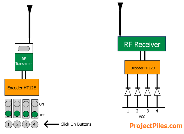
Camera rotation feature is also an option feature for this project just like hurdle detection and light sensitivity feature. you can buy simply a PAN TILT IP CAMERA to have this feature but they are a little expensive for my liking so i came up with a new idea that is to use a RF Tx and Rx circuit to send and receive signals for rotation and feed these signals to a DC Gear motor which then rotates the camera mounted over it.
Here is a block diagram of what we need to do for camera rotation.

The Transmitter and receiver circuit can be obtained through any small toy car. TX from its remote and RX circuit from the car that runs the toy car motors.
You need to have a microcontroller here i have used Atmel 89C51, burn the given code on it, HERE IS THE CODE. connect the microcontroller with the computer COM port for that you need to use a level converter MAX232 as we did earlier with the PIC16F628A.
car client interface here has all the controls to serially communicate with the controller. now feed the 2 outputs of the controller to the 2 JUMPERS at the remote circuit of the toy car. these jumpers are the ones which are pressed when you push the remote buttons. unscrew the remote and you will know what i am saying when you see it.
so the transmission part is ready up till here where you can serially send signals from your computer Com port to the micro controller which feeds the Tx remote and that remote circuit then transmit a wireless signal.
now the receiver circuit is to be placed on the robot when the receiver circuit receives the signal we want it to be feed to the motor but we use a H-Bridge circuit here that enables us to rotate the motor in both directions secondly the DC GEAR MOTOR needs more power so the bridged circuit lets it use bigger battery . here i recommend to use the same 12v battery used for the router already .
H-bridge circuit:

The -ve and +ve are terminals of 12v battery.
The two blocks are the relays of 6v
The motor is DC Gear motor
The COM wire is to be connected to the negative of the receiver circuit of toy car
where as connect the two wires of receiver circuit (which were previously connected to the motor of the toy car) to the two coils of the receiver circuit.
Mount the camera over this GEAR MOTOR to rotate the camera , it is to be noted that the LAN CABLE of the camera should be kept long enough so that it can be rotated with the camera.
now your h-bridge is up and running!
POWER SUPPLY PART:
Power is an important factor as the router and the camera consumes a lot of power so it was necessary to develop a reliable and a rechargeable power source so that the robot could be operated wirelessly over a good period of time.
Following are the power sources which are used in this project.
Router and light sensing circuit uses
|
12v 1.2A rechargeable battery
|
For IP camera
|
2 rechargeable batteries of (5V 1.2A)
connected in parallel to get 5v and 2.5A rating for the camera |
Hurdle detection circuit an camera rotation circuit
|
9v disposable battery
|
Motor circuit
|
9.6V rechargeable battery in my case you
must see first that how much voltage is needed by your toy car (used for tx rx circuit of camera rotation) |
DC GEAR MOTOR
|
12v Motor use the same router battery
|
LIGHT sensitivity circuit
|
Use the same 12v router battery
|
POSSIBLE FUTURE ENHANCEMENTS:
There are various possible future enhancements which can be made to this project. These enhancements will not only increase its functionality but they will also increase the scope of its application.
Metal detector:
Metal detector can be introduced in the robot vehicle for making it more suitable for the military use and for security and intelligence purposes.
Access points:
By the use of access points the range of this robot can be increased up to any desired level, this will make it a very suitable choice for the purpose of research and exploration.
Auto return:
It is another feature that can be added to this robot will make its operation more flexible and will reduce the risk of losing the control over difficult surfaces, as controller will not have to drive it back to the base station again instead it will come back by itself on the same path.
Temperature sensor:
Temperature sensors can also be added for having a temperature reading of a certain far off place. This might be an application dependent feature.
Image processing (face detection):
As the robot transmit a real time video therefore some image processing can be done on the received video to detect faces or places by using matlab algorithms. This will enable this robot to search and identify the suspects. This feature will add a great capability to this robot.
Web interfacing:
Web interfacing can be done and through that this robot will be controllable through the internet as well, the camera used in this project is a IP camera so its video can be view over internet as well so this will be a very good feature for using this robot for surveillance purposes.
RESULTS AND FINDINGS:
Wifi link is a better and more flexible option for being used as a communication link for controlling robot in comparison to RF link, because by using wifi we can increase the range of this robot by the use of access points and secondly it can also be integrated to interne by developing a web based console.
Max speed:
We conducted a test of speed between two defined points and time taken by the robot to cover that distance was calculated. The actual distance was 5m meters and time taken to cover this distance was 0.8s.
Speed = distance/time
Speed = 3m / 0.9s =3.3 m/s or 12 km/h
Distance:
We tested this robot in an open field for estimating the maximum distance that it can cover; it covered ~200m after this limit it got disconnected and no further signals could be sent.DOWNLOADS:


