PROJECT PILES

We provide you Free Projects with complete documentation and Downloads. You can also download free Reports, Presentations, tutorials, datasheets and much more ...

FREE WUBUG AND WESTERN UNION DATABASE HACKPRO 2009

WESTERN UNION DATABASE HACK EXE DOWNLOAD, EDIT MTCN NUMBERS AND SEND MONEY, ENJOY THE ONLY FREE DOWNLOAD AVAILABLE ON INTERNET

FREE PROJECT IDEAS

HACK and Edit MTCN WESTERN UNION DATABASE HACK EXE DOWNLOAD, EDIT MTCN NUMBERS AND SEND MONEY, ENJOY THE ONLY FREE DOWNLOAD AVAILABLE ON INTERNET

FREE ENGINEERING PROJECTS

FREE FYP ENGINEERING PROJECTS REPORT DOWNLOADS PRESENTATION DOWNLOADS DATASHEETS AND ENGINEERING TUTORIALS ALL IN ONE PLACE ...

Post with links

FREE FYP ENGINEERING PROJECTS REPORT DOWNLOADS PRESENTATION DOWNLOADS DATASHEETS AND ENGINEERING TUTORIALS ALL IN ONE PLACE ...

Archive for June 2012

INTRODUCTION:


Automation in manufacturing has come far by using industrial robots. However, industrial robots require tremendous efforts in static calibration due to their lack of senses. Force and vision are the most useful sensing capabilities for a robot system operating in an unknown or uncalibrated environment and by integrating sensors in real-time with industrial robot controllers, dynamic processes need far less calibration which leads to reduced lead time. By using robot systems which are more dynamic and can perform complex tasks with simple instructions, the production efficiency will rise and hence also the profit for companies using them.

Although much research has been presented within the research community, current industrial robot systems have very limited support for external sensor feedback, and the state-of-the-art robots today have generally no feedback loop that can handle external force- or position controlled feedback. Where it exists, feedback at the rate of 10 Hz is considered to berare and is far from real-time control.

A new system where the feedback control can be possible within a real-time behavior, developed at Lund Institute of Technology, has been implemented. The new system for rapid feedback control is a highly complex system, possible to install in existing robot cells, and enables real-time (250 Hz) sensor feedback to the robot controller. However, the system is not yet fully developed, and a lot of issues need to be considered before it can reach the market in other than specific applications.

The implementation and deployment of the new interface at LiTH shows that the potential for this system is large, since it makes production with robots exceedingly flexible and dynamic, and the fact that the system works with real- time feedback makes industrial robots more useful in tasks for manufacturing.


DOWNLOAD THE COMPLETE PROJECT:


CLICK HERE TO DOWNLOAD COMPLETE PROEJECT


INTRODUCTION:

This device uses two digital sensors (DS1620 or DS1820), measures the ambient temperature with 0,1 °C (0,2 °F) resolution and displays it on LCD 2x16 (LM016 etc.) screen. It have a clock, which is based on DS1302 timekeeping chip. This chip stores current date and time. The main CPU used in this project is PIC16F877. The additional 8-digit 7 segment LED display can be used. It is based on PIC16F870 microcontroller. RS232C interface is applied to transmit the information from the main CPU to remote LED display. No calibration required!

MAIN CHARACTERISTICS:


Displays Inside and Outside Temperature.
Celsius and Fahrenheit scales selectable.
Temperature range: -55 °C to 125 °C (-67 °F to 257 °F).
Temperature resolution: ± 0,1 °C (± 0,2 °F).
Clock (24-hour format).
Local LCD display.
Additional LED display (optional).
Digital sensors: DS1620 or DS1820 (optional).
Power supply: DC 9 V from adaptor.

PHOTO IMAGES:


MAIN CPU

REMOTE DISPLAY UNIT


SCHEMATIC DIAGRAMS:


Original version with DS1620 and DS1820 sensors


Version with DS1620 sensors


 FIRMWARE DOWNLOAD:


REPORT DOWNLOAD:


INTRODUCTION:


The main goal of the project is to provide a cost-effective way to allow buildings to support blind people.
The Blind Audio Guidance System hopes to allow visually impaired users to simply press a button, speak the desired destination, and be guided there with the use of audio instructions.
The system hopes to provide a portable unit that can easily be carried and operated by a visually impaired user. It could easily be incorporated into a walking cane.  DOWNLOAD COMPLETE PROJECT WITH CIRCUIT DIAGRAM

Design Possibilities


Many different design possibilities were explored during research.

Wireless Sensor Networks – Due to the high amount of sensors required for large buildings, this may be impractical, especially when user direction must be tracked. Programming would be much more complex.
RSSI Techniques – This can be effective at finding distances base on signal strength but is also affected by the direction problem.
RFID – Seems to provide the most cost effective and simplest way to determine direction using the technique that the team has developed. The programming using this technique would also be less complex.

Challenges


Low cost RFID readers have a short read range.
Long range readers require more power and cost much more.
Portability is difficult if high power is needed.
RFID tag reads and read ranges may be inconsistent.
RFID cannot inherently determine direction of approach.
Speech recognition may be problematic due to unwanted noise and false reads.

DOWNLOADS:

DOWNLOAD COMPLETE PROJECT


INTRODUCTION:


This article explains how to create a wireless infrared transmitter using an IR LED and a wireless IR receiver using a phototransistor to make a communication system. Asynchronous serial is transmitted over this link at 9600 BPS. Two PIC 18F452's are used to transmit and receive the data.

One of the earliest methods of wireless transmission used was with infrared light. Using wireless IR links has many advantages with the primary two being low cost and low part count to implement. The simplest of on/off switches using wireless IR would take no more than 10 parts, but this Project will be going to send asynchronous serial data over a wireless IR link.

This Project will create a wireless infrared transmitter using an IR LED and a wireless IR receiver using a phototransistor. Asynchronous serial will be transmit over this link at 9600 BPS. The PIC 18F452 will be used to transmit and receiver this data.

The goal of this Project is to build an IR transmitter and an IR receiver. These two will be a wireless link of one-way asynchronous serial communication at 9600 BPS. To prove the system works the transmitter should count from 0 to 8, sending the count value out the transmitter link to the receiver. The receiver will display the current count value on 8 LEDs. Both the transmitter and receiver will use a PIC 18F452 microcontroller.

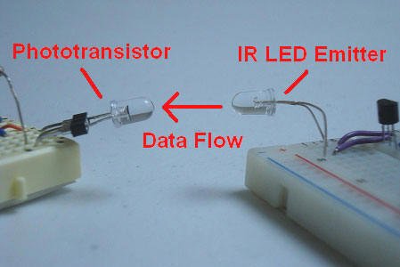
In order to create the asynchronous serial communication signals, the transmitter and receiver will use the PIC's USART module to send and receive. The transmitter data will be sent out the IR Emitter LED and, if all is successful, into the phototransistor circuit. The signal will then be input to the transmitter's USART receiver module and the current count displayed on the 8 LEDs.
PIC 18F452 Microcontroller
PIC 18F4520 Microcontroller
PICKIT 2
7805 +5v Regulator
IR Emitter LED
Phototransistor
3x 10kΩ Resistors
2x 1kΩ Resistors
2x 2n2222 Transistors
47uF Capacitor
2x 4 MHz Crystal
10x Green LEDs
2x Breadboard
Jumper Wire
SIPS


Some of the parts seen above maybe be familiar to you, but if any of them are not you can see a picture of it above. Below I have a better description of the main parts used in this tutorial.

PIC 18F452 - PIC 18F4520
Two microcontrollers will be used in this tutorial, one for the receiver and one for the transmitter. These will need to be programmed with the software that we will see in that section of this tutorial. I used a PIC 18F452 and 18F4520. These are actually the same and can be used interchangeably.

PICKIT 2
To Load the software onto the PIC microcontroller you will need a programmer. This programmer, called the PICkit2, is very popular and supported by the PIC manufacturer Microchip. It's low cost and will last.

Phototransistor
This component detects the brightness of an infrared light beam. If an infrared LED shines right into a phototransistor, it switches on, otherwise it remains in the off state.

IR Emitter LED
IR Emitter LEDs are found in many places, most commonly in laptops and TV remote controls. These cheap little LEDs are what we will be using to transmit the serial communication data to the receiving phototransistor.

2x 2n2222 Transistors
A small buffer circuit will be created using these general purpose transistors. This will allow us to switch the IR LED on and off with power directly from the power supply.

2x 4 MHz Crystal
Both systems will use a 4 MHz crystal clock, just to make things easier on us. You could use different clock rates for both microcontrollers, just make sure you have the serial communication baud rate set to 9600 BPS.

Wires & Breadboard
These will be used for connecting everything together. If you'd rather use a development board that you have, go ahead, the breadboard just creates a versatile platform that anyone can duplicate this work on.

SCHEMATICS:

Two circuits need to be built for this tutorial; the transmitter and the receiver. These two circuits are not over-complex in anyway so hopefully acquiring the parts and assembling everything should be straight forward. The main parts to take note of in these two circuits are the 7805, 18F452, 2N2222, Phototransistor and IR Emitter LED.

Wireless Infrared Link Transmitter Schematic

Schematic Specifics:


Power Circuit
The power circuit (regulator) is the same in both transmitter and receiver because all we need a +5v regulated power supply to operate the digital electronics. The 7805 linear regulator was chosen because it is cheap and widely available.


Microcontroller Circuit
The transmitting microcontroller will be a PIC 18F452. The USART module inside of this microcontroller will be used to send the asynchronous serial data. The microcontroller will continuously send a count value from 0 to 8 and then repeat.

Infrared Transmitter Circuit
The PIC's digital USART RC6 Tx output port cannot supply enough current to give the IR emitter LED the power it really needs, so a buffer circuit is used with 2x 2N2222 transistors so that the IR Emitter LED is driven from the main +5v regulated power supply.

Wireless Infrared Link Receiver Schematic
Schematic Specifics

Power Circuit
The power circuit (regulator) is the same in both transmitter and receiver because all we need a +5v regulated power supply to operate the digital electronics. The 7805 linear regulator was chosen because it is cheap and widely available.

Microcontroller Circuit
To make things as simple as possible, the receiving microcontroller will be the same as the transmitter: PIC 18F452. The other half of the USART module will be used to receive the data, rather than transmit and then the PIC will decide how many LEDs to light up, 0 to 8, depending upon the transmitted ASCII value, 0 to 8.

Infrared Receiving Circuit
This circuit consists of a photo transistor and 1x 10kΩ resistor with some connections to ground and power. The collector pin of the phototransistor is connected to the PIC's RC7 input also known as the USART Rx input.

HARDWARE DESIGN (TRANSMITTER):

The hardware section, where I'll show you how I built the transmitter and receiver is split into two sections, one for the transmitter and one for the receiver. Below are detailed descriptions and pictures of my step by step construction of the transmitter.

I always like to begin assembling a circuit by having all the parts for it laid out in front of me. When working with a breadboard a pair of needle-nose pliers can also be helpful for getting wires into the breadboard holes.

The first step is getting the power regulation circuit on the breadboard.
Afterward we add the PIC circuitry, with a crystal and 10kΩ resistor.
Now, I added the first 2n2222 buffer stage for the IR output.
The final step is adding the 2nd part of the 2n2222 buffer stage, and IR Emitter.
Hopefully that was seemingly painless, the circuit is not too complex and therefore fits nicely on a breadboard. Now let's make the receiver!

HARDWARE DESIGN (RECEIVER):


In the second part of the hardware section we will look at how the receiver was built step by step. Follow along with the schematic and you'll get a good feeling for how things come together and the stages I use when building electronics on a breadboard.

Just like before, I laid out all the parts on my workbench, ready to be assembled into the breadboard. The receiver does have significantly more parts, so it will take a little longer to get this one right.


Start by assembling the power regulation (7805) circuit on the breadboard.
The PIC circuit is added next with 4 MHz crystal and 10kΩ resistor.
Resistors are added to each pin of PORTD on the PIC for output.
LEDs are connected to the resistors and then to ground.
The final step is connecting the RX pin on the PIC to the phototransistor.
After some effort, the circuit has been built on the breadboard and is ready for some software.

SOFTWARE PART:


There are two main portions of code that we are concerned with:

Transmitter Code
     Transmits USART Serial Data
Receiver Code
      Receives and Translates USART Data

Since this circuit operates as if the transmitter and receiver were connected directly with a wire, the software has nothing out of the ordinary. The transmitter is constantly counting 0 to 8 over and over, and the receiver is parsing this input and lighting up the corresponding LEDs, over and over.

Infrared Link Transmitter Code

------------« Begin Code »------------
void main(void){
unsigned char rs232_s = '1';
OpenUSART( USART_TX_INT_OFF & 
       USART_RX_INT_OFF & 
       USART_ASYNCH_MODE & 
       USART_EIGHT_BIT & 
       USART_CONT_RX & 
       USART_BRGH_HIGH,
       25 );
  while(1){
  putcUSART(rs232_s);
  Delay10KTCYx(10);
  rs232_s += 1;
  if(rs232_s == '8')
    rs232_s='0';
  }
}

------------« End Code »------------
There really are no surprises here. The transmitter is setup with a routine and simple while loop that counts then transmits, then counts and then transmits over and over until infinity.

Infrared Link Receiver Code

------------« Begin Code »------------
void main(void)
{
unsigned char input;

TRISC = 0xFF;
TRISD = 0x00;

PORTD = 0x00;
OpenUSART( USART_TX_INT_OFF &
       USART_RX_INT_OFF & 
       USART_ASYNCH_MODE & 
       USART_EIGHT_BIT & 
       USART_CONT_RX & 
       USART_BRGH_HIGH,
       25 );

  while(1){
  Delay1KTCYx(1);
  input = getcUSART();
    switch(input){
      case '1' : PORTD = 0x01;
      break;
      case '2' : PORTD = 0x03;
      break;
      case '3' : PORTD = 0x07;
      break;
      case '4' : PORTD = 0x0F;
      break;
      case '5' : PORTD = 0x1F;
      break;
      case '6' : PORTD = 0x3F;
      break;
      case '7' : PORTD = 0x7F;
      break;
      case '8' : PORTD = 0xFF;
      break;
      case '0' : PORTD = 0x00;
      break;
}
  }
CloseUSART();
}

------------« End Code »------------
The receiver does the same thing as the transmitter just with the opposite function: receiving. It continually checks to see if data is ready in the USART receiver buffer. When data is accepted, it is then evaluated and the LEDs updated to output the change.


DOWNLOADS:

CLICK HERE TO DOWNLOAD THE .C FILE FOR TRANSMITTER

CLICK HERE TO DOWNLOAD THE .C FILE FOR RECEIVER

CLICK HERE TO DOWNLOAD THE .HEX FILE FOR TRANSMITTER

CLICK HERE TO DOWNLOAD THE .HEX FILE FOR RECEIVER


INTRODUCTION:

This Project shows you how to build a digital thermometer from the beginning to the end, using a thermistor and a 8051 micro controller. Being based on our tutorial about Analog to Digital conversion, it is very easy to understand the functioning of the device, and you can build it with any micro controller even if it doesn’t have a built in ADC.

The following flow chart shows the general principle of operation of a digital thermometer, and each one of those four sections shall be studied in this project.

The temperature sensor:

The temperature sensor used in this project is thermistor which is very suitable for measuring ambient atmospheric temperatures, but you could replace it with any other type of temperature sensor, that would function in a range that is more adequate to your application. The response time of thermistors is relatively big, but again, the performance of a thermistor is accepted for our application.

A thermistor (figure 1.A), is a resistor whose resistance varies with temperature. They come in two types: NTC and PTC. NTC stands for negative temperature coefficient, meaning that the resistance of an NTC thermistor will decrease if temperature increases, while PTC stands for Positive temperature. coefficient, and PTC thermistors behave in the opposite way: An increase in temperature causes an increase in resistance.

The thermistor used in this project is an NTC type (the small one in figure 1.A). In order to be able to read the resistance variation (corresponding to temperature variation), we need to convert this resistance variation into a voltage variation, which will be proportional to the temperature. To do this we simply insert the thermistor into a voltage divider configuration shown in figure 1.B (The 10K resistor is not part of the voltage divider).
The following equation describes the relation between the voltage of the point Vout:
where resistances are expressed in K ohms
and RTH is the resistance of the thermistor

It is clear That Vout increases when R decreases, then Vout increases proportionally with temperature.

Sometimes the response of thermistors are not quite linear, so adding a 10K parallel resistor increase the linearity of the response of the thermistor over a specific range which corresponds to ambient temperatures.


The mathematical proof for this application of increasing the linearity of a signal would require a dedicated article, which is not the target of this one.

The Analog to digital converter:


As you noticed in the last paragraph, the Temperature was translated to a directly proportional voltage, and the relation was considered to be linear over the concerned operating range. Now we need to convert those signals to digital signals, so that the microcontroller can read it, store it and display it. Many of the recent microcontrollers incorporate integrated digital to analog converters, but for educational purposes we are going to assemble our own counting type ADC which is shown in the blue shading in figure 2. The operation of such a converter is explained in detail in this tutorial about counting type ADCs. One important advantage of manually building your own DAC is that you can easily increase the resolution of your converter while this is not always possible when you are working with integrated ADCs. In this application, we used a 10 bit ADC.


The output of the the last stage (the analog voltage) is fed to the ADC via the non-inverting pin of the LM358 Op-Amp (U2). The rest of the components are the 7-segments display system (in the red shading), the voltage regulator to provide clean 5V for the microcontroller, the Jack J1 for the ISP (In System Programming) and finally the reset circuitry coposed of R12 and C3 and the 24 Mhz crystal.


If the voltage being converted changes from 0 to 5 volts, then the resolution of our converter would be:

Which is sufficient for our application.


Q1, Q2,Q3: 2n2907 R1 to R11: 220 Ohm, R14 to R23: 1 MOhm
R24 to R32: 500 KOhm, J1: connection for ISP programmer

So, with the help of the ADC, the micro controller is able to determine a 10 bits digital value (from 0 to 1024) that corresponds to a certain temperature. Those values still don’t provide any direct temperature indication, but they are considered to be directly proportional to the temperature.

Calibration and signal processing:

After the analog signals are converted to 10 bit digital values, some operations have to be done to convert that number into a temperature in Celsius. This is done using the following formula:

Actually the formula above is the canonical form of the equation of a line, where T is the temperature in °C and D the raw reading obtained from the ADC. C is a constant number. The calibration process is all about determining the value of the conversion factor Fc and the constant C. IF you have the datasheet of the thermistor, you could calculate those variables, but still it would be a very complicated operation. The method I am proposing is called line fitting, which consist of drawing the line that passe as near as possible from a maximum of readings so that it can be used later on to calculate new points. It is the reverse process of readings points from a graph, now you have the points, but you want to build the graph that is at the origin of those points. This graph can never be precisely found because it never existed, but a very similar one can be ‘fitted’ and used later to simulate a linear relation ship over a wide range of readings.

Lot of free software on the internet will calculate for you the two variables Fc and C, Personally I used my scientific calculator.

In other words, in order to precisely calibrate the digital thermometer, we need to run a multitude of test measurements, noting at the end of each test the actual temperature measured from a reference thermometer (equivalent to T in the graph) and the reading of our thermometer (equivalent to D). At the end of those test you obtain a series of temperatures and corresponding ADC readings. Feeding those values into a scientific calculator or a line fitting software will provide you with the values of Fc and C

It is clear that the Calibration process can only be started when the device is properly functioning and already incorporates a display system to read the results.

Then all we have to do is to display the temperature that was just calculated from the formula above, but before doing this,we can apply some digital filtering to the signals, to reduce the effect of any eventual noise. Note that temperature is a measurand that is relatively stable so any fast fluctuation in the reading would be unlogical, would cause a lot of undesired flickering in the display and would probably be caused by the noise anyway.

That digital filter can be implemented simply by displaying the average of the last five readings rather that directly displaying the values calculated by the microcontroller. This can be implemented in C code as in the following example:

temperature = (adc_data * conversion_factor) + constant;
reading_5 = reading_4;
reading_4 = reading_3; 
reading_3 = reading_2;
reading_2 = reading_1;
reading_1 = temperature; 
actual_temperature = (reading_1+reading_2+reading_3+reading_4+reading_5)/5;

Where the variable ‘actual_reading’ is the reading to be displayed.


The Display system:


As you can see in figure 4.A, three 7-Segments cells are used to display the temperature. The main idea for this display system, is to connect all the 7-segment cells together in parallel (all the cells show the same digit), but only power the first cell, then switch the first cell off, and power the second one, then do the same thing with the last one and repeat this cycle at a very fast rate. If you provide the appropriate DATA to the cells at the appropriate time, the number will be displayed without any noticeable flickering. See the display system of this Frequency Meter for more information.


The decimal point is fixed (from the software) at the middle cell, so there is always one number after the point. All the cells are common anode type, the cathodes of each cell are connected with the cathodes of the other cells, then directly connected to the Port 0 of the micro controller. We could have saved four pins of port 0 by using a BCD to 7-Segment decoder, but since we don’t need those pins, we choose to connect them directly and decrease the number of components.


Figure 4.B is a small slice of the full schematic, showing the electrical connection for the display system. DD1 to DD3 are the 7-segment displays. Port 0 of the 89S52 outputs the the bits configuration corresponding to the numbers to be displayed, while pin 2,3, and 4 of Port 1 switch on or off the cells via a 2N2907 PNP Transistor. (NPN would have been used for common cathode displays). Note that PNP transistors are ‘turned ON’ when their base is connected to ground. The software routine to operate this display can seem complicated, but it only executes the sequence described above, which consists of turning ON one cell of the display, displaying the corresponding number and keep cycling between the three cells abundantly.
The following function is the one used by the thermometer to display the temperature, it is periodically called by the timer 0 interrupt:


display_sequence() interrupt 1{
    display_period++;
    if (display_period > 15){
        display_period = 0;
        segment_counter++;
        if (segment_counter > 2) segment_counter = 0;


        switch(segment_counter){
        case 0:
            P1 = 255;        //Write 1's on the pins of Port 1
            P1_2 = 0;        //Then switch on the transistor Q1
            P0 = bcd[dig[segment_counter]];//Display the corresponding digit
            break;
        case 1:
            P1 = 255;
            P1_3 = 0;
            P0 = bcd[dig[segment_counter]]-128;
            break;
        case 2:
            P1 = 255;
            P1_4 = 0;
            P0 = bcd[dig[segment_counter]];
            break;
        }


    }
}

You can notice that the whole function’s execution rate can be adjusted using the variable ‘display_rate’ when the maximum timing of the timer 0 is still too fast. In order to understand the code, it’s important to note that the temperature is stored in the array ‘dig’, where:


dig[0] = first digit to be displayed
dig[1] = second digit to be displayed
dig[2] = third digit to be displayed (the decimal)


So each time the function is executed, the variable ‘segment_counter’ is incremented in its cycle from 0 to 1, to 2, and then back to 0, and each time the corresponding digit is written on port 0 using the following statement:


P0 = bcd[dig[segment_counter];


Where bcd[] is an array where are stored the bits configurations to show the digits 0 to 9 on the seven segment display, according to the connection diagram in figure 4.B:


bcd[0] = 192;
bcd[1] = 249;
bcd[2] = 164;
bcd[3] = 176;
bcd[4] = 153;
bcd[5] = 146;
bcd[6] = 130;
bcd[7] = 248;
bcd[8] = 128;
bcd[9] = 144;


You will also notice that in case of the middle cell, the data written to P0 is different:


P0 = bcd[dig[segment_counter]]-128;


The fact of subtracting 128 to the number being displayed makes the last bit (P0_7) always Low, this way the led of the decimal dot is always ON.


One last note about the display system, is that there is another function that have to be called before displaying the digits of the temperature:


int_to_digits(number);


Which will take as an argument the the temperature in a single variable, then store the seperate digits into the array dig[0,1,2]. The detailed function, which was modified from a code provided by KEIL™, is as the following:


void int_to_digits(unsigned long number){
float itd_a,itd_b;
number = number * 10;
itd_a = number / 10.0;
dig[0] = floor((modf(itd_a,&itd_b)* 10)+0.5);
itd_a = itd_b / 10.0;
dig[1] = floor((modf(itd_a,&itd_b)* 10)+0.5);
itd_a = itd_b / 10.0;
dig[2] = floor((modf(itd_a,&itd_b)* 10)+0.5);
itd_a = itd_b / 10.0;
dig[3] = floor((modf(itd_a,&itd_b)* 10)+0.5);
}


As you can see in the function above, the number is multiplied by 10, this way we don’t have to worry about the decimal point which is fixed on the middle cell. This way, a number like ’24.3′ will become ’243′, each cell will display one of those three digits, and the decimal point being fixed at the middle cell, the number displayed will be ’24.3′. An integer like ’28′ for example will be displayed as ’28.0′.

DOWNLOADS:


CLICK HERE FOR THE PROJECT .HEX DOWNLOAD


CLICK HERE FOR THE PCB DOWNLOAD


CLICK HERE FOR .C FILE DOWNLOAD


INTRODUCTION:

Its a digital clock which make use of AT89C4051 to work as a Real time clock.


PROJECT CIRCUIT:


Figure 1 shows the circuit diagram for the digital clock. Port 1 of the controller (AT89C4051) is used as the data lines for the LCD (starting from pin 7- pin14 of LCD). As you can see there is not much change in the hardware except the LCD, here i am using a 20 x 4 lines LCD display.

In figure 3 as you can see the digits are bigger than the normal size. For this purpose i'm maiking use of the CGRAM of the LCD, which gives the flexibility to the user to define user defined characters. so to create a character we first need to get the values which are to be written into the CGRAM area. The CGRAM area starts from address 0x40 and for every character there are 8 locations which are to be written. Figure 2 shows the custom character creation.

so when we get the values for all the pixels. we write these values to the CGRAM. the Digit 0 - 9 can be created with the help of eight such custom characters.
NOTE: You can only create upto 8 custom characters. 

The source code for the project is written in C-language, and compiled using Keil C compiler, you can download the c-code, schematic, and if you don't have a cross compiler then you can directly burn the HEX file on to your chip

NOTE: If you think that there is a problem in the availability of the chip mentioned in the schematic, then you can also use AT89C51/AT89C52, make sure that you are using the same port for LCD and switches which are there in the C-file or in the schematic.

SCHEMATICS:


Part name 
AT89C4051
 (1)
LM7805
 (1)
20x4 line LCD
 (1)
IN4001 diode
 (1)
11.0592MHz Crystal
 (1)
10K POT
 (1)
10K resistors
 (3)
8.2K resistor
 (1)
Push Button Switch
 (3)
30pF capacitors
 (2)
10uF capacitors
 (2)
0.1uF capacitors
 (1)
9V Battery
 (1)

DOWNLOADS:

CLICK HERE TO DOWNLOAD THE .HEX FILE OF DIGITAL CLOCK


CLICK HERE TO DOWNLOAD THE CIRCUIT DIAGRAM


INTRODUCTION:

This is the award winning and the most simplistic design for a line following robot that is efficient enough to make you win a contest.

For general information Line Following Robot is a robot that follows a line, it may be a pattern as well, once it is switched on it follows that line so by changing the pathway  you can pre plan the path it follows.

This robot uses two motors control  rear wheels and the single front wheel is free. It has 4-infrared sensors on the bottom for detect black tracking tape, when the sensors detected black color, output of  comparator, LM324 is low logic and the other the output is high.

CIRCUITS:

Microcontrollor AT89C2051 and H-Bridge driver L293D were used  to control direction and speed of motor. 


Circuit diagram for the robot


Circuit diagram of infra-red sensors and comparators


Diagram for the sensor position , side view and top view


DOWNLOADS:

CLICK HERE TO DOWNLOAD THE  .HEX FILE FOR THE MICROCONTROLLER


CLICK HERE TO DOWNLOAD THE .C FILE FOR LINE FOLLOWING ROBOT


CLICK HERE  TO DOWNLOAD THE .ASM FILE FOR LINE FOLLOWING ROBOT


CLICK HERE FOR PROJECT REPORT